|
 |
|||||||||||
 |
|
|||||||||||
 |
 |
|||||||||||


|
Next: 2.11 Continuity and horizontal Up: 2.10 Spatial discretization of Previous: 2.10.6 Vertical grid Contents 2.10.7 Topography: partially filled cells
[5] presented two alternatives to the step-wise finite difference representation of topography. The method is known to the engineering community as intersecting boundary method. It involves allowing the boundary to intersect a grid of cells thereby modifying the shape of those cells intersected. We suggested allowing the topography to take on a piece-wise linear representation (shaved cells) or a simpler piecewise constant representation (partial step). Both show dramatic improvements in solution compared to the traditional full step representation, the piece-wise linear being the best. However, the storage requirements are excessive so the simpler piece-wise constant or partial-step method is all that is currently supported.
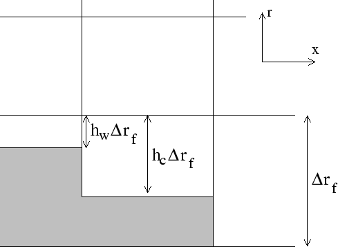
Fig. 2.11 shows a schematic of the x-r plane indicating how
the thickness of a level is determined at tracer and u points.
The physical thickness of a tracer cell is given by
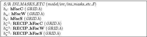
The non-dimensional fractions (or h-facs as we call them) are
calculated from the model depth array and then processed to avoid tiny
volumes. The rule is that if a fraction is less than hFacMin
then it is rounded to the nearer of 0 or hFacMin or if the
physical thickness is less than hFacMinDr then it is similarly
rounded. The larger of the two methods is used when there is a
conflict. By setting hFacMinDr equal to or larger than the
thinnest nominal layers,
Next: 2.11 Continuity and horizontal Up: 2.10 Spatial discretization of Previous: 2.10.6 Vertical grid Contents mitgcm-support@dev.mitgcm.org
|
||||||