|
 |
|||||||||||
 |
|
|||||||||||
 |
 |
|||||||||||


|
Next: 2.10.7 Topography: partially filled Up: 2.10 Spatial discretization of Previous: 2.10.5 Horizontal grid Contents 2.10.6 Vertical grid
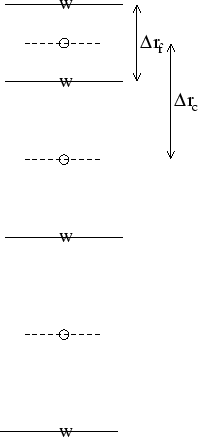
As for the horizontal grid, we use the suffixes ``c'' and ``f'' to
indicates faces and centers. Fig. 2.10a shows the default
vertical grid used by the model.
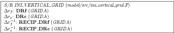
The vertical grid is calculated in subroutine INI_VERTICAL_GRID and specified via the vector DELR in namelist PARM04. The units of ``r'' are either meters or Pascals depending on the isomorphism being used which in turn is dependent only on the choice of equation of state. There are alternative namelist vectors DELZ and DELP which dictate whether z- or p- coordinates are to be used but we intend to phase this out since they are redundant.
The reciprocals
The above grid (Fig. 2.10a) is known as the cell centered
approach because the tracer points are at cell centers; the cell
centers are mid-way between the cell interfaces.
This discretization is selected when the thickness of the
levels are provided (delR, parameter file data,
namelist PARM04)
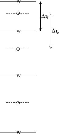
An alternative, the vertex or interface centered approach, is shown in
Fig. 2.10b. Here, the interior interfaces are positioned
mid-way between the tracer nodes (no longer cell centers). This
approach is formally more accurate for evaluation of hydrostatic
pressure and vertical advection but historically the cell centered
approach has been used. An alternative form of subroutine INI_VERTICAL_GRID is used to select the interface centered approach
This form requires to specify
Next: 2.10.7 Topography: partially filled Up: 2.10 Spatial discretization of Previous: 2.10.5 Horizontal grid Contents mitgcm-support@dev.mitgcm.org
|
||||||||